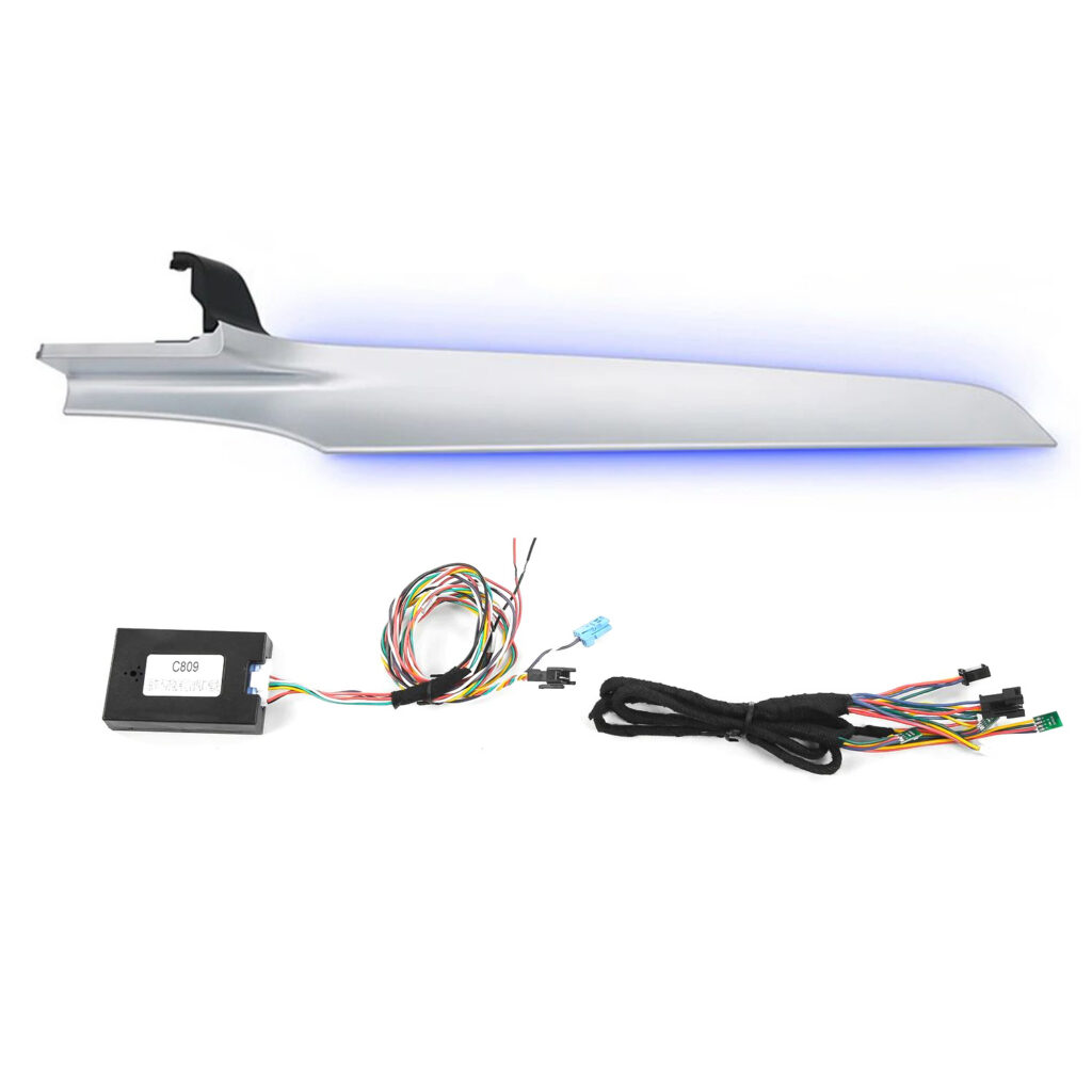
This guide describes replacement of the illuminated passenger-side trim for Mercedes-Benz C-Class W205 and GLC 253. The installation information lists a combined 2015–2021 vehicle range; confirm the exact vehicle, trim, kit revision and ambient-light configuration before installation. Factory and retrofitted ambient lighting require matching connections or modules.
1. Illustrated trim replacement
The illustration shows releasing the center-console chrome trim clips, removing the T20 retaining screws and lifting the console panel while keeping it level. It then shows removal of the center speaker grille, the display retaining screws and the display, followed by removal of the passenger trim from the center outward. Transfer the original metal clips to the replacement illuminated trim.
The final wiring example joins the trim lighting to already-installed front illuminated vents. If those vents are absent, use the separate module arrangement described below. Confirm the actual module and harness before connecting; the guide does not provide a vehicle-specific terminal map or complete procedure for disconnecting the display and refitting the trim.
Figure 1. View full-size
2. Lighting setup and troubleshooting
-
If the vehicle has factory ambient lighting and no other illuminated products have been added, the front passenger ambient light requires a separate module for driving it.
-
If the vehicle has factory ambient lighting and illuminated air vents have been added, connect the front passenger ambient-light wiring together with the added illuminated-air-vent wiring.
-
If the colors are not synchronized, set the ambient-light color palette to the basic colors: red, green, and blue. If one color is missing, check its wiring and connector as well as the LED unit. Confirm the fault before replacing the LED unit.
-
If the front passenger ambient light does not light up at all, check whether the main-harness plug has come loose and whether the adapter or joined-wire terminals match the actual kit connection definitions. This guide does not specify a universal terminal assignment or joining method.
-
Occasionally, the wire colors may differ during wiring. Refer to the wiring diagram below. The following table describes the product harness and the other harness in the illustrated example.
| Product harness: wire color and function | Other harness: color in the illustrated example |
|---|---|
| Yellow — positive supply | Yellow |
| Red — red lighting channel | Green |
| Green — green lighting channel | White |
| Blue — blue lighting channel | Red |
This is the color correspondence shown for these two example harnesses. Confirm connector terminals, polarity and lighting-channel functions for the actual kit before making a connection. Wire colors alone do not identify a universal pinout or electrical standard.
Figure 2. View full-size
Spot an error or an unclear step? Please contact the CKCP representative who supplied this guide and include the guide ID, step or image number, or video timestamp. Your vehicle model and year can help us check the issue.
CKCP tutorial reference: CKCP source archive